Individual Fin Model#
- Author:
Mateus Stano Junqueira
- Date:
March 2025
Introduction#
There are currently three ways to model the aerodynamic effects of fins in RocketPy:
By use of the
rocketpy.GenericSurfaceorrocketpy.LinearGenericSurfaceclasses, which are defined by receiving the aerodynamic coefficients directly;By use of the
rocketpy.Finsclasses (rocketpy.TrapezoidalFins,rocketpy.EllipticalFins,rocketpy.FreeFormFins), which are defined by receiving the geometric parameters of the fin set and calculating the aerodynamic coefficients internally with the Barrowman method;By use of the
rocketpy.Finclasses (rocketpy.TrapezoidalFin,rocketpy.EllipticalFin,rocketpy.FreeFormFin) (which are the base classes for the fin set classes), which are defined by receiving the geometric parameters of one single fin and calculating the aerodynamic coefficients internally with the Barrowman method, with exception of the moment coefficients, which have been derived in this document.
This document will focus on all the mathematical derivations and implementations
of the rocketpy.Fin classes.
Fin Coordinate Frame#
The fin coordinate frame is defined as follows:
The origin is at the leading edge of the fin, at the intersection of the fin’s root chord and the fin’s leading edge;
The z-axis is aligned with the fin’s root chord, pointing towards the fin’s trailing edge;
The y-axis is aligned with the fin’s span, pointing towards the fin’s tip chord;
The x-axis completes the right-handed coordinate system.
The fin is postioned at the rocket’s body, given a rocket_radius \(r\),
an angular_position \(\Gamma\) and a position \(p\) along the
rocket’s body. The angular position is given according to
Angular Position Inputs.
The fin can also be rotated by a cant angle \(\delta\).
The image below shows the fin coordinate frame:

Note
A positive cant angle \(\delta\) produces a negative body axis rolling moment at zero angle of attack.
The rotation matrix from the fin coordinate frame to the rocket’s body frame is define by, first a rotation around the y-axis by 180 degrees:
Then a rotation around the z-axis by the angle \(\Gamma\):
Then a rotation around the y-axis by the cant angle \(\delta\):
The final rotation matrix is given by:
The position of the fin’s coordinate frame origin in the rocket’s body frame is calculated by first assuming no a fin frame with no cant angle, then calculating the position of the fin’s leading edge (with cant angle) in this frame, and finally translating this position to the fin’s position in the rocket’s body frame. The position of the fin’s real leading edge in this no cant angle fin frame is given by the point \(\mathbf{P}^{\delta}_{le_f}\):
Then, describing this point to the rocket’s body frame orientation (no translation):
The position of the fin’s leading edge with no cant angle in the rocket’s body frame is given by:
Finally, we add the position of the fin’s leading edge with no cant angle to the position of the fin’s leading edge with cant angle in the rocket’s body frame:
Center of Pressure Position#
In the Fin Coordinate Frame, the center of pressure is given by the Barrowman method, and will here only be defined symbolically:
The center of pressure position in the rocket’s body frame is given by:
Aerodynamic Forces#
Note
The aerodynamic coefficients are defined according the Barrowman method.
Given a stream velocity in the fin frame \(\mathbf{v}_{0f} = [v_{0x}, v_{0y}, v_{0z}]^{T}\), the effective angle of attack of the fin is given by:
This can also be seen as the angle between the fin’s root chord and the stream velocity vector in the fin frame.
The aerodynamic force in the x-direction of the fin is given by:
Where \(A_{r}\) is the reference area of the fin, and \(C_{N}\) is the normal force coefficient, which is a function of the angle of attack and the Mach number \(Ma\). This force is then transformed to the rocket’s body frame by the rotation matrix:
Then, the moments are calculated by the cross product of the center of pressure and the aerodynamic force:
From the Barrowman method, the moment along the center axis of the rocket (\(M_{z}\)) is still missing the damping term, which is given by:
Where \(C_{ld}\) is the roll moment damping coefficient, \(L_{r}\) is the reference length, which is equal to the rocket diameter, and \(\omega_z\) is the angular velocity of the rocket around the z-axis.
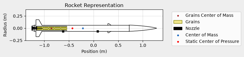
Adding Individual Fins to the Rocket#
Given a defined Rocket object, we can add individual fins to the rocket by
using the add_surfaces method. Here is an example of adding two canards
in the Calisto rocket from the First Simulation example:
canard1 = TrapezoidalFin(
    angular_position=0,
    root_chord=0.060,
    tip_chord=0.020,
    span=0.03,
    rocket_radius=example_rocket.radius,
    cant_angle=0.5,
    airfoil=("../data/airfoils/NACA0012-radians.txt", "radians"),
)
canard2 = TrapezoidalFin(
    angular_position=180,
    root_chord=0.060,
    tip_chord=0.020,
    span=0.03,
    rocket_radius=example_rocket.radius,
    cant_angle=0.5,
    airfoil=("../data/airfoils/NACA0012-radians.txt", "radians"),
)

# Position along the center axis of the rocket is specified here.
# If different positions are desired, the position can be specified as a list.
example_rocket.add_surfaces([canard1, canard2], positions = 0.35)

example_rocket.draw(plane="yz")
See also
There are three classes for defining fins in RocketPy given their geometry:
rocketpy.TrapezoidalFin- For how to define a trapezoidal finrocketpy.EllipticalFin- For how to define an elliptical finrocketpy.FreeFormFin- For how to define a free form fin
Fin Force Conventions#
Here we exemplify the fin force conventions relating the cant angle (deflection angle) of the fins to the pitch, yaw and roll moments. We will consider a rocket with four fins, to illustrate the concepts. The image below show the sign convention for the forces acting on the fins, given positive cant angles:

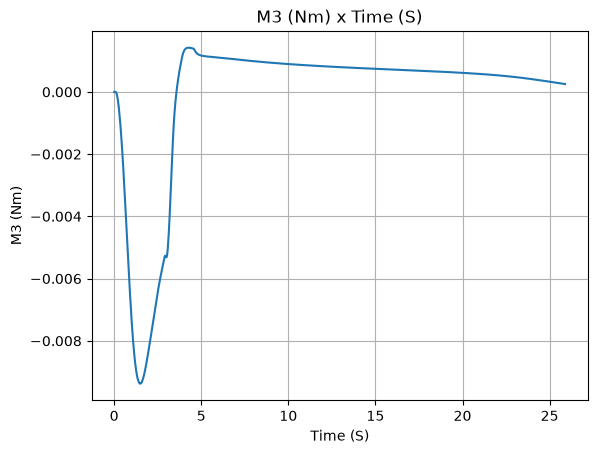
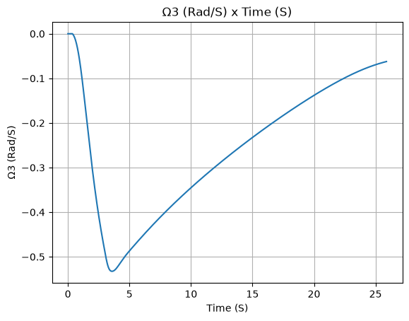
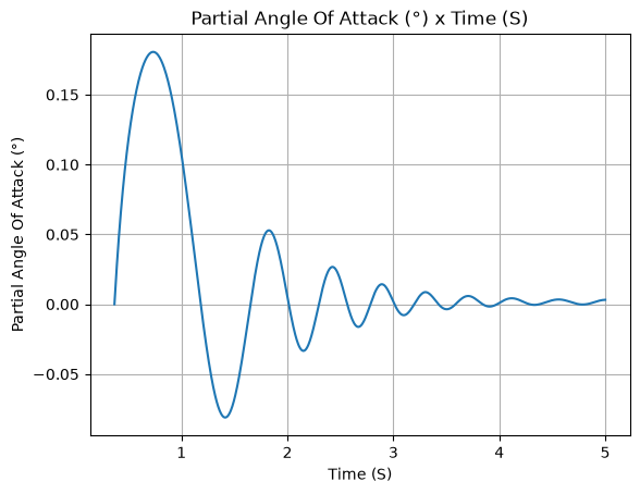
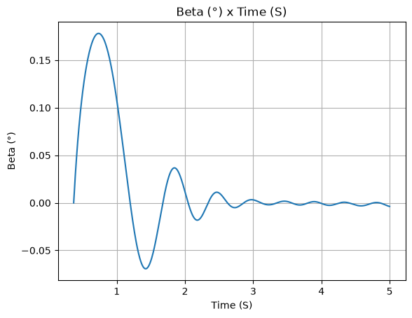
Roll#
A positive cant angle \(\delta\) produces a negative roll moment at zero angle of attack. Any fin with a positive cant angle will produce a negative roll moment, and any fin with a negative cant angle will produce a positive roll moment.
Here is a flight of the calisto with canards defined with a positive cant angle:
canard1 = TrapezoidalFin(
    angular_position=0,
    root_chord=0.060,
    tip_chord=0.020,
    span=0.03,
    rocket_radius=example_rocket.radius,
    cant_angle=0.5,
    airfoil=("../data/airfoils/NACA0012-radians.txt", "radians"),
)
canard2 = TrapezoidalFin(
    angular_position=180,
    root_chord=0.060,
    tip_chord=0.020,
    span=0.03,
    rocket_radius=example_rocket.radius,
    cant_angle=0.5,
    airfoil=("../data/airfoils/NACA0012-radians.txt", "radians"),
)

example_rocket.add_surfaces([canard1, canard2], positions = 0.35)

test_flight = Flight(
    rocket=example_rocket,
    environment=env, rail_length=5.2, inclination=85, heading=0,
    terminate_on_apogee=True,
)

# Rolling Moment
test_flight.M3()

# Rolling Speed
test_flight.w3()

# Angle of attack
test_flight.partial_angle_of_attack.plot(test_flight.out_of_rail_time, 5)

# Angle of sideslip
test_flight.angle_of_sideslip.plot(test_flight.out_of_rail_time, 5)
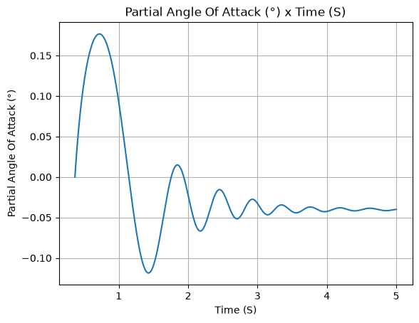
Pitch#
Given canards fins at 90 degrees and 270 degrees, having opposite cant angles, a positive pitch moment will be generated. The following example shows the effect of this configuration in the non-zero angle of attack flight of the rocket:
canard1 = TrapezoidalFin(
    angular_position=90,
    root_chord=0.060,
    tip_chord=0.020,
    span=0.03,
    rocket_radius=example_rocket.radius,
    cant_angle=0.5,
    airfoil=("../data/airfoils/NACA0012-radians.txt", "radians"),
)
canard2 = TrapezoidalFin(
    angular_position=270,
    root_chord=0.060,
    tip_chord=0.020,
    span=0.03,
    rocket_radius=example_rocket.radius,
    cant_angle=-0.5,
    airfoil=("../data/airfoils/NACA0012-radians.txt", "radians"),
)

example_rocket.add_surfaces([canard1, canard2], positions = 0.35)

test_flight = Flight(
    rocket=example_rocket,
    environment=env, rail_length=5.2, inclination=85, heading=0,
    terminate_on_apogee=True,
)

# Angle of attack
test_flight.partial_angle_of_attack.plot(test_flight.out_of_rail_time, 5)

# Angle of sideslip
test_flight.angle_of_sideslip.plot(test_flight.out_of_rail_time, 5)
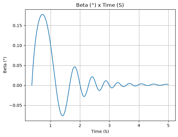
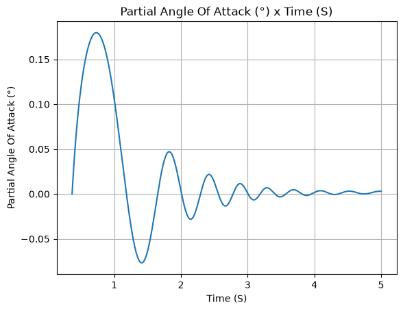
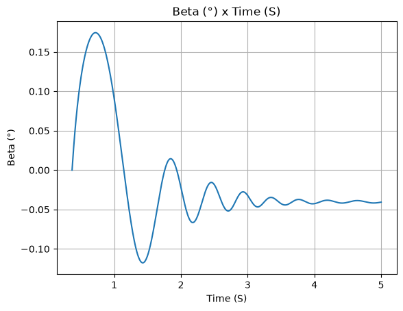
Yaw#
Given opposing canards at 0 degrees and 180 degrees, having opposite cant angles, a positive yaw moment will be generated. The following example shows the effect of this configuration in the non-zero angle of attack flight of the rocket:
canard1 = TrapezoidalFin(
    angular_position=0,
    root_chord=0.060,
    tip_chord=0.020,
    span=0.03,
    rocket_radius=example_rocket.radius,
    cant_angle=0.5,
    airfoil=("../data/airfoils/NACA0012-radians.txt", "radians"),
)
canard2 = TrapezoidalFin(
    angular_position=180,
    root_chord=0.060,
    tip_chord=0.020,
    span=0.03,
    rocket_radius=example_rocket.radius,
    cant_angle=-0.5,
    airfoil=("../data/airfoils/NACA0012-radians.txt", "radians"),
)

example_rocket.add_surfaces([canard1, canard2], positions = 0.35)

test_flight = Flight(
    rocket=example_rocket,
    environment=env, rail_length=5.2, inclination=85, heading=0,
    terminate_on_apogee=True,
)

# Angle of attack
test_flight.partial_angle_of_attack.plot(test_flight.out_of_rail_time, 5)

# Angle of sideslip
test_flight.angle_of_sideslip.plot(test_flight.out_of_rail_time, 5)