Roll equations for high-powered rockets#
- Author:
Bruno Abdulklech Sorban,
- Author:
Mateus Stano Junqueira
- Date:
February 2022
Nomenclature#
\(A_{r}\) - Reference area
\((C_{N\alpha})_{0}\) - Normal force coefficient derivative of a 2D airfoil
\((C_{N\alpha})_{1}\) - Normal force coefficient derivative of one fin
\(C_r\) - Root chord
\(C_t\) - Tip Chord
\(F\) - Force
\(L_{r}\) - Reference length, rocket diameter
\(M_{roll}\) - Roll moment
\(M_{f}\) - Roll forcing moment
\(M_{d}\) - Roll damping moment
\(N\) - Number of fins
\(\overline{q}\) - Dynamic pressure
\(r_t\) - Reference radius at fins position
\(s\) - Span
\(v_{0}\) - Rocket speed in relation to the wind
\(\omega\) - Angular velocity
\(Y_{MA}\) - Spanwise location of mean aerodynamic chord measured from the root chord
\(\delta\) - Fin cant angle
\(\xi\) - Distance to rotation axis
\(\rho\) - Ambient density
\(C_{lf}\) - Roll moment lift coefficient
\(C_{lf\delta}\) - Roll moment lift coefficient derivative
\(C_{ld}\) - Roll moment damping coefficient
\(C_{ld\omega}\) - Roll moment damping coefficient derivative
Introduction#
Calculating the rotational movement of a high powered rocket entails calculating the Roll Moment. Here all formulas and consideration for the implementation of the Roll Moment in RocketPy are shown and explained.
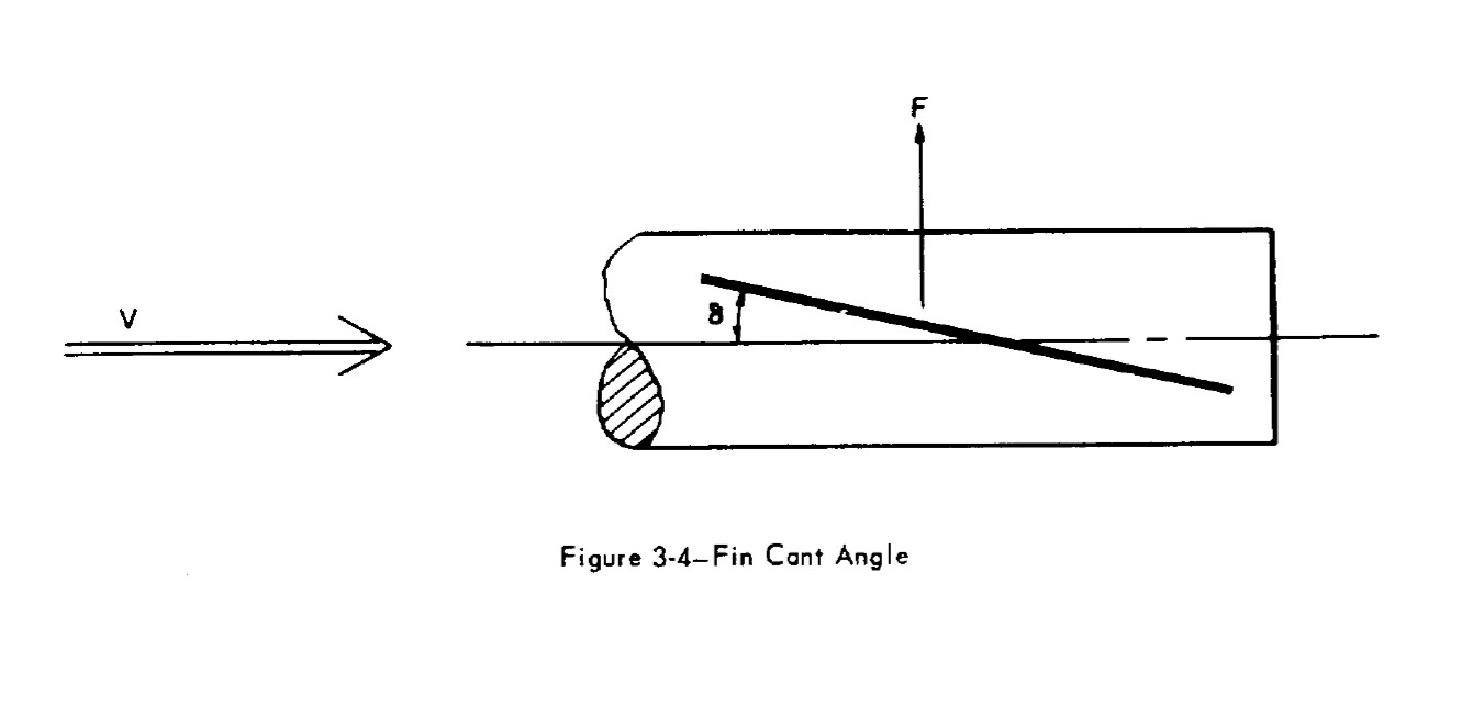
The main cause for a rocket roll movement are certain asymmetries in its construction. The most noteworthy of this possible asymmetries is the fin cant angle (\(\delta\)), which can be seen in Figure 1, and will be considered for the calculations.

Coefficient derivatives#
According to the equation formulated by [Barrowman], the rotational moment around the rockets axis is governed by two main forces: one that causes the rolling movement and one that damps the movement. Each of these forces generates its own moment, the forcing moment \(M_{f}\) and the damping moment \(M_d\). The final roll moment can then be calculated with:
Roll Forcing#
Roll forcing is the moment that causes the rocket to rotate around its axis. The calculations for this moment assumes \(\omega = 0\) e \(\delta \neq 0\).
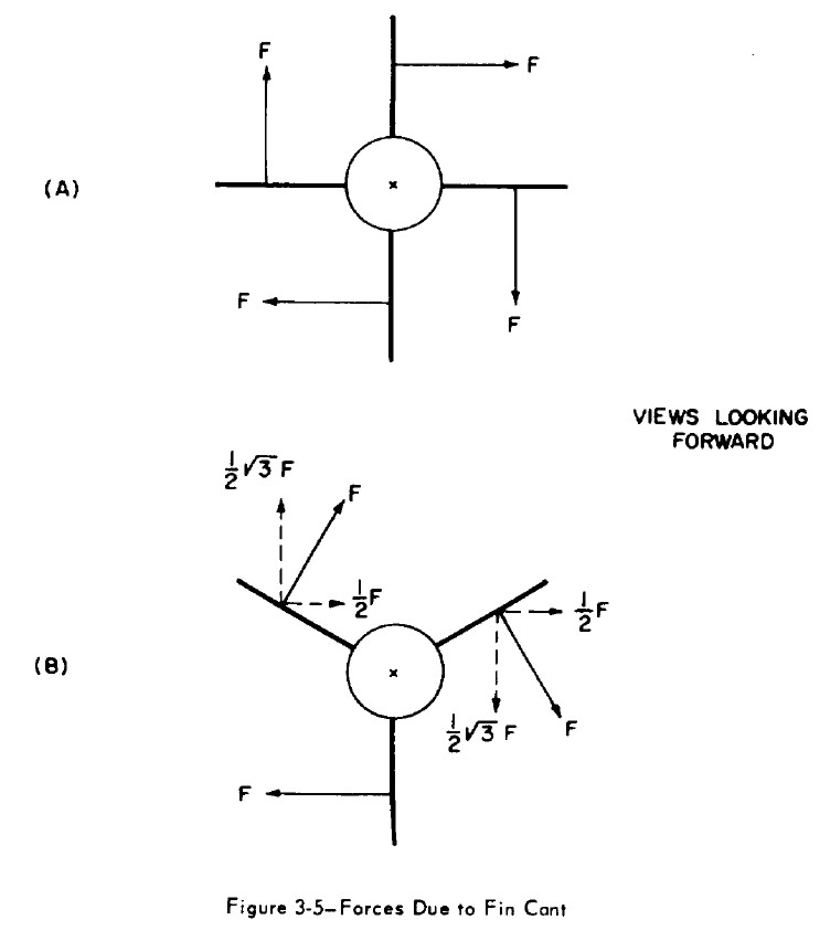
Due to the symmetry of the fins - as can be seen in Figure 2 - the forces cancel each other out so that the resulting force \(F_{R}\) is equal to zero. However, the resulting moment \(M_{R} \neq 0\), that is, it constitutes a gyroscope binary.

According to [Barrowman], equation (3-31), the roll forcing moment is given by:
The author also defined the roll forcing moment coefficient as:
The letter “\(f\)” has been added to the name to differentiate Forcing from Damping. Note the similarity with the definition of drag coefficient (\(C_{d} = \frac{2F_{Drag}}{\rho V^2 A_{ref}}\)). Finally, you can also calculate \(C_{lf}\) as:
And its derivative relative to the cant angle as:
The forcing moment is then calculated with:
or
Roll Damping#
While roll forcing causes the rotation movement, the roll damping force is what counteracts this movement. It is a force that scales with angular velocity and acts in the opposite direction. \(\omega \neq 0\) and \(\delta = 0\) are assumed.
It is defined in the same way as roll forcing:
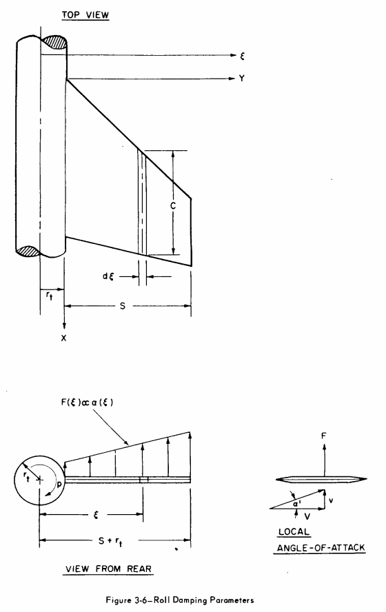
From [Barrowman], the roll damping moment depends on the angle of attack of the tangential velocity of the fin panel at a certain span wise position \(\xi\), as can be seen in Figure 3.

The damping moment at \(\xi\) is:
Where \(F(\xi)\) is the force generated at the span wise position \(\xi\) and its given by:
\(a(\xi)\) is the local angle of attack at \(\xi\) and is given by:
An approximation that is valid when \(v_0 >> \omega \, \xi\) is made
\(c(\xi)\) is the cord length at the span wise \(\xi\) and is calculated differently for each fin shape. The damping moment can then be written as:
From [9] we know that:
Integrating over the exposed fin geometry:
The initial hypothesis assumes that, for the roll damping calculation, the deflection is \(\delta = 0\). This implies a larger cross-sectional area than is actually acting against the movement (analogous to flow passing through a surface). As a result, the term \(\cos(\delta)\) was added to the original formulation:
The roll damping coefficient derivative can then be defined as:
Finally, \(C_{N_{\alpha 0}}\) must be corrected for three dimensional effects:
The values of the definite integral can be calculated for each specific fin shape. For trapezoidal fins:
And for ellipsoidal fins:
The damping moment is finally:
Interference Coefficients#
In [Barrowman] some fin-body interference factor are calculated. These factors are also implemented in the lift coefficient calculations.
For fins with canted angle:
For the damping moment lift coefficient derivative:
Comments#
Roll moment is expected to increase linearly with velocity. This relationship can be verified in the rotation frequency equilibrium equation, described by [Niskanen] in equation (3.73), and again stated below:
The auxiliary value \(\beta\) is defined as: \(\beta = \sqrt{|1-M|}\), where M is the speed of the rocket in Mach.